At the light it connects to the neutral terminal. A switch and outlet combo can be configured in several ways.

Wiring Diagram Light Switch Receptacle
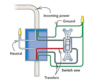
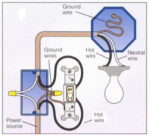
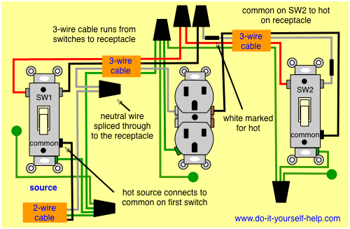
How to wire a light switch and outlet. Switch can control the light only. It depends how you want the switch and receptacle to function. Two wire cable runs from the light to sw1 and 3 wire cable runs between sw1 and sw2. Now remove the wire cap from the two white wires in the box add the white wire from the outlet and reset the cap. The following diagrams show each wiring configuration. When a white wire is used for hot like this its marked with black tape or paint at the ends to identify it as hot.
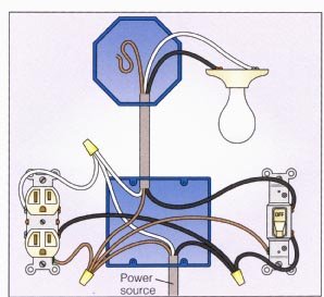
Locate a nearby electrical outlet or junction box that the recessed light switch and the recessed light will be wired to. Use the black wire as the power in. Remove the black line wire from the switch twist it together with the black wire going to the receptacle and add a six inch length of black wire of the same gauge. Switch can control the light and outlet. Wiring a switch to an outlet in this wiring a switch is added to to an existing outlet by removing the hot wire from outlet brass terminal and connected to the first terminal of switch. The second terminal of switch then connected back to the brass terminal of outlet.
This way the outlet is wired and controlled onoff through the switch. The hot source wire is spliced at the light box to the white cable wire running to the first switch box. Mark the wire wire with black electrical tape at each end and use it for the power out. To do this you have to join together the black wires neutral wires and ground wires so that you have one connection for each using pigtails. With this example these two wires are configured to break the circuit power and send the power to the switch and then back to the outlet. Replacing or upgrading a light switch is a simple and inexpensive diy project.
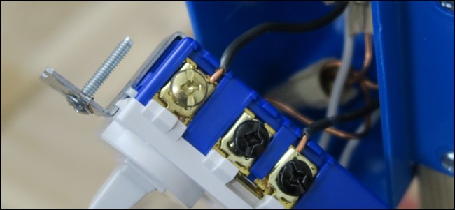
On the other hand if you simply w. How to wire a switch and outlet combo. The source neutral wire is spliced to the neutral on the receptacle half of the combo device and to the white cable wire running to the light. Connect this jumper wire back to the switch terminal. Remove the face plate from the outlet or junction box. Switch and the outlet can have different lines in.
Alternatively you can wire the switch up in such a way that only that single outlet will be controlled by the switch but other outlets in the circuit will still stay powered on constantly. There it is spliced to the black wire running to the second switch box which is then connected to the common terminal on sw2. If you want the receptacle to be powered all the time and want to use the switch to control a load other than the receptacle you wire it like this. Ground connection diagram is shown separately. Two wire cable runs from the combo to the light fixture and the switch output is connected to the black wire running to the fixture hot terminal.


