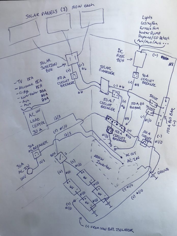
Complete guide on designing and installing your own diy electrical system in a camper van conversion. Keystone rv wiring diagram keystone cougar rv wiring diagram keystone rv cable tv wiring diagram keystone rv tv wiring diagram every electric structure consists of various distinct parts.

Trailer Wiring Diagram Lights Brakes Routing Wires
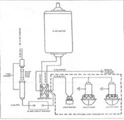
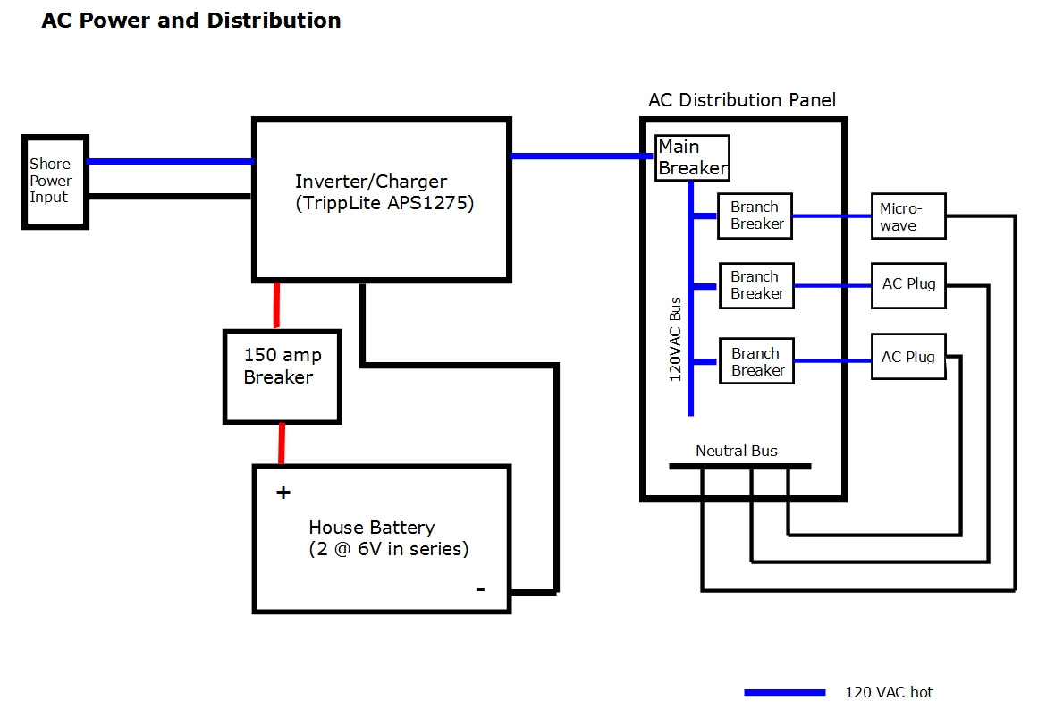
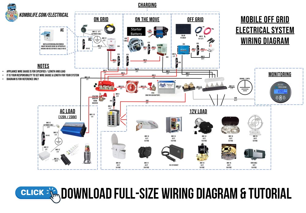
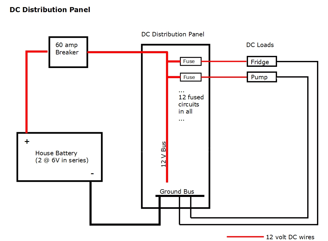
Camper electrical wiring diagram. Here is the definite electrical wiring diagram for the conversion of your camper van skoolie rv etc. Rv electrical diagram wiring schematic understanding you campers electrical wiring can be very confusing. Truck camper 6 pin umbilical wiring july 22 in order for a truck camper to be street legal it must have an electrical interface with the trucks running stop turn signal and backup electrical circuits. A 12 volt dc electrical system and a 120 volt ac system. Collection of travel trailer wiring schematic. Interactive wiring diagram for camper van skoolie rv etc.
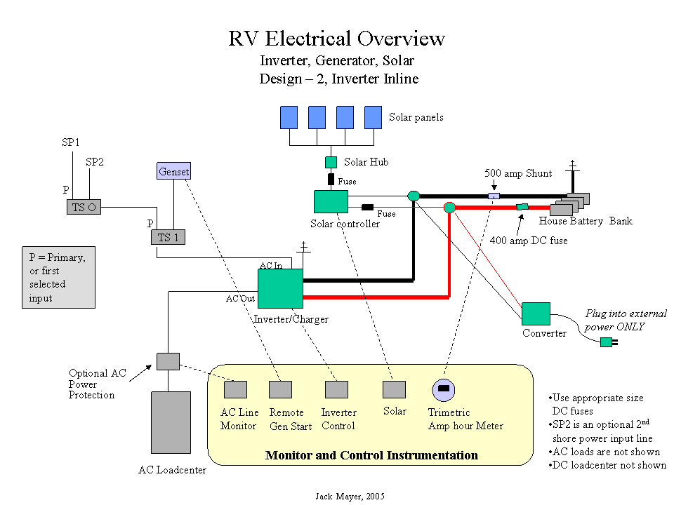
The 12 volt system is powered by a battery or in some cases multiple batteries and it powers things such as the start up on your water heater furnace and refrigerator plus most of the lights in your rvs living space your water pump your carbon. You almost certainly know already that lance camper plug wiring diagram is among the most popular topics on the web now. One rv two electrical systems. Wiring diagram od rv park 1995 fleetwood southwind rv wiring diagram a newbie s overview of circuit diagrams a very first appearance at a circuit representation may be complicated but if you could check out a train map you can review schematics. Now since your stick and brick house has only 120 volt ac we immediately know an rv is different therefore the rv electricity systems within an rv should only be worked on by someone qualified to do so. Use the rv electrical diagram we made below to get an understanding of what powers what and to learn how an rv electrical system works.
A wiring diagram is a streamlined traditional photographic depiction of an electric circuit. Your rv has two separate electrical systems. It reveals the parts of the circuit as streamlined shapes as well as the power and also signal links in between the gadgets. That said for specific situations there are industrial standards with different connectors and wire arrangements. The following trailer wiring diagrams and explanations are a cross between an electrical schematic and wiring on a trailer. We recommend these standards because they are pretty universal.
Free wiring diagram and tutorial inside. Each part should be set and linked to different parts in particular manner. Otherwise the arrangement will not function as it should be. It is designed with flexibility in mind so feel free to adddelete any charge source. Solar power alternator or shore power.


