The tunnel circuit control the lamps in four ways as follow. The condition of getting output.

Bw 1838 Wiring A Light Switch And Outlet On Same Circuit
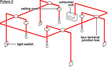
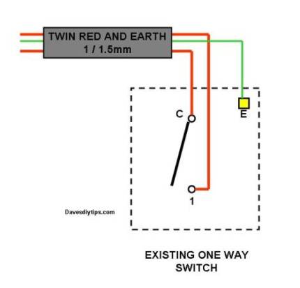
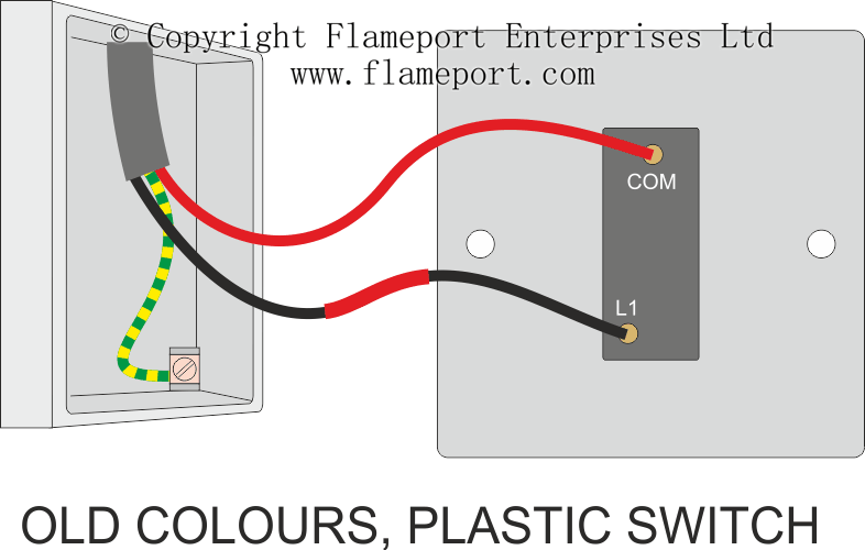
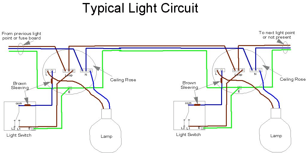
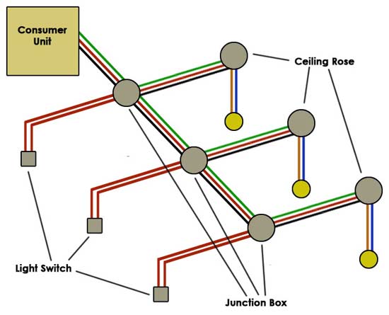
Wiring a light circuit. Turn and brake circuits 30 amps this product ships directly from the manufacturer. The second system in popular use is the junction box circuit or system. Sometimes called a loop in circuit this shows how power is distributed around the lighting circuit via the ceiling roses or junction boxes and how to wire a light switch into the circuit. Once you have mastered the basics we take a look at the two way switch arrangement. This circuit is wired with a 2 wire cable running from the light to the switch location. A cable is run from the junction box to the light usually via a ceiling rose.
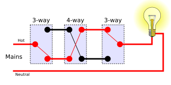
In 3 wire control method when switches are in same state the light will be in off state as shown in circuit below. Parallel or series parallel wiring method is more reliable instead of series wiring. Connecting electrical devices and appliances like fan outlet light bulbs etc in parallel is a prefer way instead of series wiring. Tunnel wiring circuit is used in open ended corridors and short tunnels like structures. The common household circuits used in electrical wiring installation are and should be in parallel. The other end of the lamp is connected with neutral line of ac power supply.
In tunnel wring circuit diagram we have used spdt two way switches to control the lighting points in tunnels and corridors. The average handling time on this item is 10 days. Wiring a switch loop when the electrical source originates at a light fixture and is controlled from a remote location a switch loop is used. Curt 56402 custom wiring harness 3 wire system 4 way flat tail light circuit 70. The live is interrupted by the switch wiring and the circuit is carried on to the next junction box. Mostly switches outlet receptacles and light points etc are connected in parallel to maintain the power supply to other electrical devices and appliances through hot and neutral wire in case if one of them gets fail.
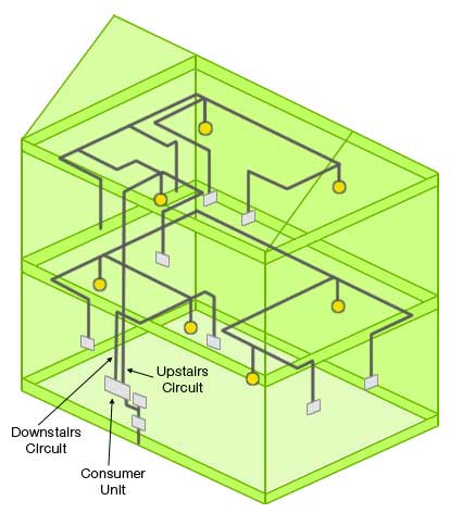
This is where you can control the same light via two switches. Light control circuit by switches for patient in hospital rooms we call it hospital wiring circuit by using only switches and lamps to control the lighting density of bulbs in a room especially for admitted patients in the hospital. From the iconic mail order catalog to a fully stocked digital commerce experience we have built a preferred destination for every gear head professional racer weekend warrior and restoration nut. Switches and fuses must be connected through line live wire. Pin1 of both the switches are connected with the phase or live wire and pin2 of both the switches are connected with the one end of the lamp. Power is taken from the consumer unit to the first junction box.
Tail light circuit 70 amps. As you can see in the schematic diagram of 2 way switch circuit below the common of both the switches are short circuited.
