Toshiba diagrams schematics and service manuals download for free. Products include electric motors and motor controls adjustable speed drives power electronics transmission and distribution systems and more.

Toshiba Motor Starter Wiring Diagram H1 Wiring Diagram
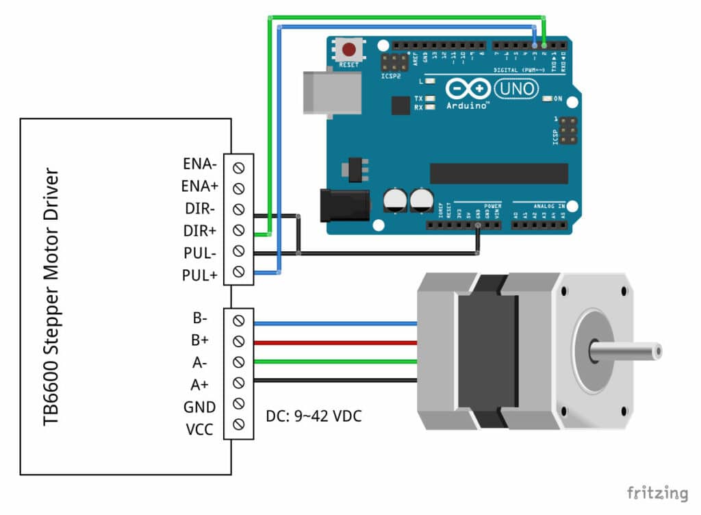
Toshiba motor wiring diagram. Single chip bipolar sinusoidal micro step stepping motor driver. Toshiba motor standardly can be driven by inverter and especially compatibles with toshiba inverter. Please contact us if you would use for the constant torque application. Zyltech toshiba tb6600 driver instructions. Confirm that transmission from indoor unit to outdoor unit is correctly performed based upon the follow ing diagram. The tb6600hg is a pwm chopper type single chip bipolar sinusoidal micro step stepping motor driver.
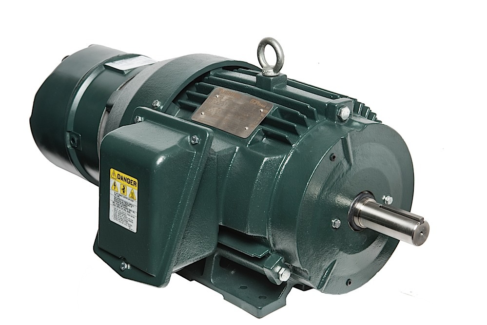
Forward and reverse rotation control is available with 2 phase 1 2 phase w1 2 phase 2w1 2 phase and 4w1 2 phase excitation modes. Eqp global motor series. For low voltage my application it indicates l1 to t1t7 l2 to t2t8 and l3 to t3t9 and then join and insulate t4t5t6. Energy saving controlling air ow of fan and water ow of pump with inverter reduces the shaft power and saves the excess energy. Toshiba international corporation tic is toshibas premiere manufacturing base in north america. 11182009 103226 am.
Voltage correspondence range of southeast asia area our motor has the following ratings. 380660v 50hz type form the following shows toshibas type. Toshibas general purpose motors are designed to meet the industrys ever increasing need for improved energy conservation and product reliability. Wiring diagram reactor cn300 main pc. How to check simple the main parts file no. Wiring diagram file no.
Mcc 1436 fan motor board reactor mcc 1571 cn200 cn609 t blu power cn201 supply thermostat circuit cn202 compressor f100 compressor t315a 250v p cn690 cn701 whi high pressure switch 250v 4way valve coil t10a 250v cn800. Toshiba connection diagrams 21 volt 75 vcq in 4 e pan at c toshiba concton the starting vhúg f4 2 second after energized e 575 ooaguims cont line g î awoss. Current limit vref x 2. Ron upper lower. 2 phase bipolar type stepping motor can be driven by only clock signal with low vibration and high efficiency. On the diagram it indicatesthat for high voltage l1 electrical leg i thinkgoes to t1 l2 to t2 and l3 to t3 and then notes to join and insulate three additional pairs of wires.
S109 uses 010ohm current sense resistor so the current limits can be calculated as follows. Connect the voltmeter to vref to the gnd and read the value. Wiring failure interconnecting and serial signal wire 1 outdoor unit does not operate 1 is the voltage between of the indoor terminal block varied. Wiring diagram motor current setting current limits can be adjusted by measuring the vref and the adjustable resistance pls check wiring diagram. Available in open drip proof totally enclosed fan cooled and totally enclosed explosion proof enclosures these motors offer the highest efficiency and torque ratings while producing some of the lowest vibration ratings in the industry leading to a longer life and greater reliability. The motor is rated 230v or 460v.
Toshiba 20vl43p lcd tv sm service manual toshiba 32wl66p 37wl66p 42wl66p 32wlg66 32wlt66 37wlg66 37wlt66 42wlg66 42wlt66 int or no audio int or no analog tv timer flash msp fault repair tips toshiba 32wl66p 37wl66p 42wl66p 32wlg66 32wlt66 37wlg66 37wlt66 42wlg66 42wlt66 no picture lines on picture flickering picture lvds t con repair tips toshiba 46 51 57h84svm service manual toshiba 46 52 62hm94svm service.
