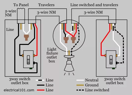
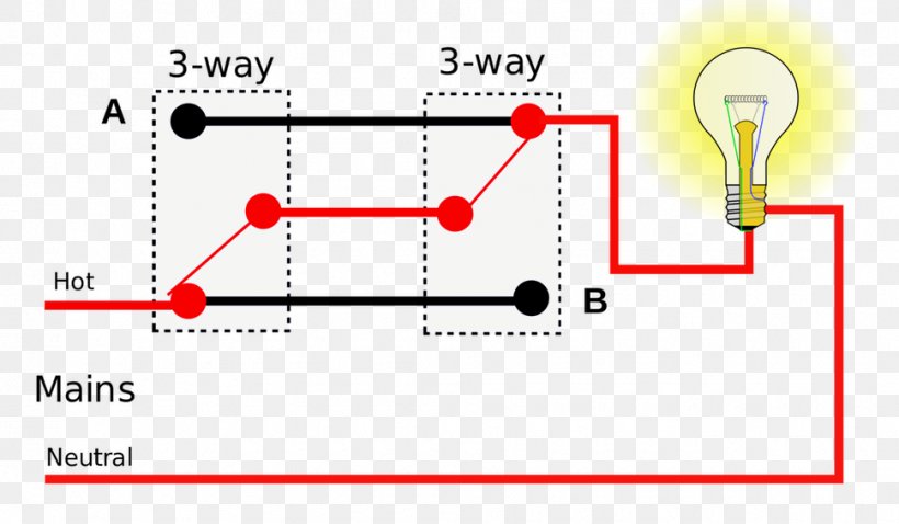
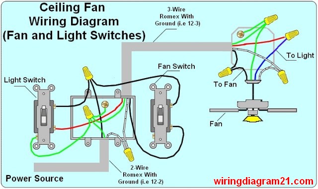
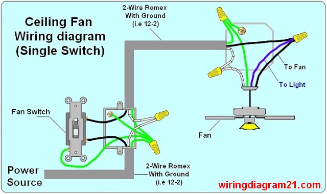
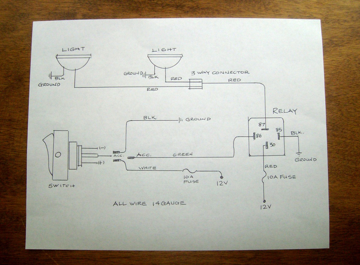
This diagram illustrates wiring for one switch to control 2 or more lights. The cable going to the light switch is connected as follows fig 2.

How To Wire An Electrical Outlet Wiring Diagram House
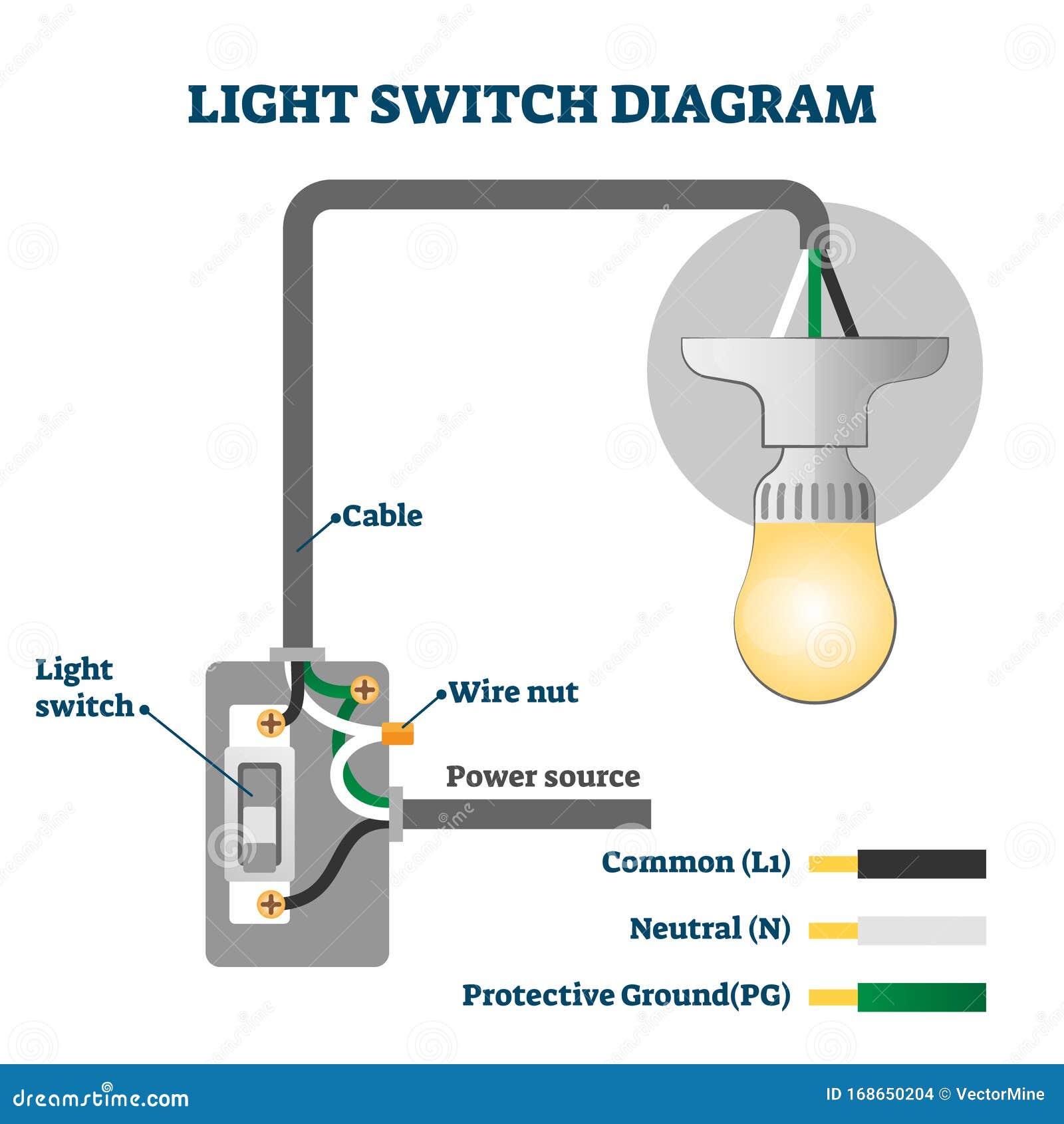
How to wire a light switch diagram. Fixture wiring exits the switch box. The source is at the outlet and a switch loop is added to a new switch. If you choose to control your overhead lighting with smart switches or dimmers youll either want to hire an electrician to install the switch or wire the light yourself. The black wire power in source attaches to one of the switch screw terminals. The black hot wires are what get connected to the light switch. The source is at sw1 and 2 wire cable runs from there to the fixtures.
This wiring diagram illustrates adding wiring for a light switch to control an existing wall outlet. The hot source wire is removed from the receptacle and spliced to the red wire running to the switch. The cable consist of a black wire a. The ground wires splice together and bond to the switch and the box. This light switch wiring diagram page will help you to master one of the most basic do it yourself projects around your house. This gauge is when you want to use the quick connect method when wiring a light switch.
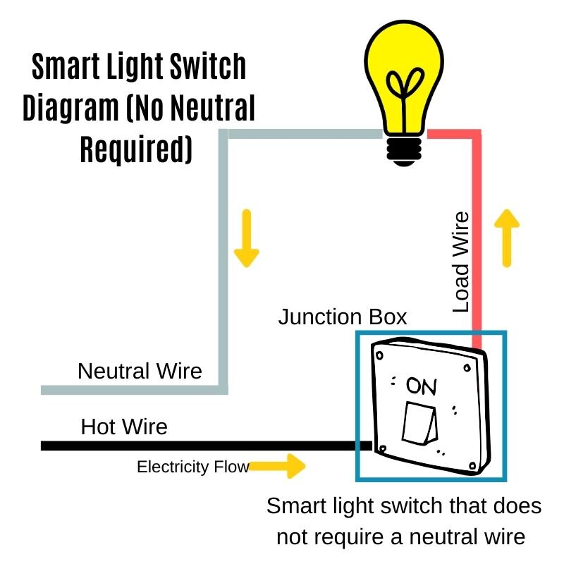
I paint a little and then work on electrical. The white neutral wire from the power source and the white neutral wire that goes to the light fixture get connected to each other. Again excuse my paint covered hands. Hey doing it yourself is great but if you are unsure of the advice given or the methods in which to job is done dont do it. Wiring a light switch is very simple. Connect the source wire to the bottom terminal of the switch and the other black wire to the top terminal.
The red wire from the feed cable is connected to the top terminal the red wire going to the light is connected to the bottom terminal the black wires from both cables are connected together in a plastic terminal block and the earth wires are connected to the earth terminal. To help guide you through wiring a light switch yourself we wanted to highlight a great post from the smartthings community posted by sidjohn1. Line diagram of a one way lighting circuit using in line method fig 1. The hot and neutral terminals on each fixture are spliced with a pigtail to the circuit wires which then continue on to the next light. In this picture you can see the strip gauge on the back of the switch. There are many ways to control and automate your lights with smartthings.
It should also help in understanding the functions of each type of switch. This site is merely. When wiring a 2 way switch circuit all youre really doing is controlling the power flow switching offon to the load a light lamp outlet ceiling fan etc now a typical circuit will contain a 3 wire cable known as romex. Simply strip the wire to the length specified and push the wire into the hole. Multiple light wiring diagram. A one way light switch is quite easy to wire up.
Wiring a single pole light switch. Wiring a 4 way switch subpanel installation this entry was posted in indoor wiring diagrams and tagged diagram do it yourself handyman handywoman home improvement home renovations home wiring house wiring light light switch power switch wiring wiring diagram. The white neutral wires splice together. The black wire power out wiring attaches to the other switch screw terminal. The black wire from the switch connects to the hot on the receptacle.
