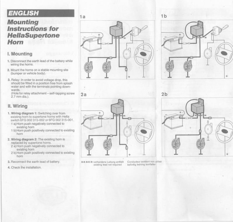
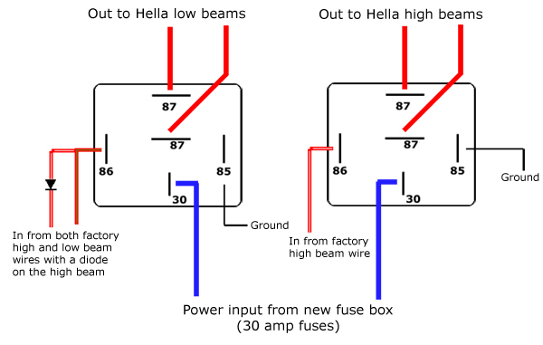
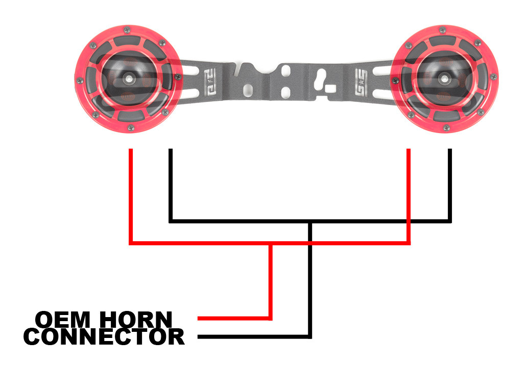
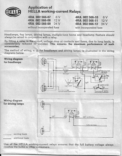
How to wire a hella 12v relay it still runs. Current controlled relay for direction indicator lamps bi stable relay for switching between low and high beam.

Piaa Fog Light Relay Wiring Diagram Wiring Diagram
Hella relay wiring diagram. Mechanical threshold voltage controller for windshield wipers 1965 e relay. To ensure a maximum relay lifetime the contact material is selected in line with the most demanding quality. 4 5 1951 first hot wire flasher unit 1960 a relay with metal housing. Relays electrics catalog hella. The first modular system 1969 wipewash interval control unit 1970 k relay. This article was written by the it still works team copy edited and fact checked.
About the author. Relays and relay devices products and applications hella. Slide this wires wire terminal onto a hella five pin relays terminal labeled 87a this terminal turns hot when the control circuit deactivates. Find best value and selection for your hella auto 12v spdt sealed relays 4rd 01 search on ebay. Four pin relays do not use this terminal see reference 2 under the common pin designations chart. Hella 550 wiring diagram wiring diagram is a simplified suitable pictorial representation of an electrical circuitit shows the components of the circuit as simplified shapes and the talent and signal associates in the midst of the devices.
Can you tell me simply the configuration to wire a relay especially how a switch is wired to the relay i think with the option to place befhella supertone horns archive singapore bikes forumssimple relay switch wiring. Hella relay wiring diagram starter. Hella relays feature diodes or resistors to suppress interrupting voltage peaks in the relay coils and thus prevent interference voltage. Hella light relay wiring diagram database. Simple relay switch wiring could you advise with the wiring of a relay hella 4ra as the technicals explain but skip over the switch placement. Wiring diagram hella 4rd 931 680 01 schematron.
Relais produkte und anwendungen hella. Mounting instructions after ascertaining desired position on front of vehicle allowing enough space for adjustment ensure that the lamps are fi tted to a rigid point of the vehicle such as the bumper bar. The electro mechanical plug in relay has been one of hellas core products for many years. As switch amplifiers used to control electrical loads in plug in standard models these electronic components can be controlled by control units. Items you will need. By ekaterina korina on june 24 2020 in wiring diagram 180 views hella relay wiring diagram starter 407 5 168 votes table of contents.
The use of a hella relay as supplied with driving and fog lamp kits when fi tted and wired as shown in the wiring diagrams see over eliminates voltage loss to the lamps ensures maximum light output and prevents overloading of the vehicles wiring and switches. May 12 the part number on the relay is 4rd this is the german hella part number. The first fully electronic flasher unit 1968 l relay.


