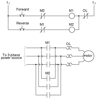
As soon as reverse contactor. The reverse contactor coil energized and three phase induction motor runs in the reverse direction.

Electrical Wiring Diagram Forward Reverse Motor Control And
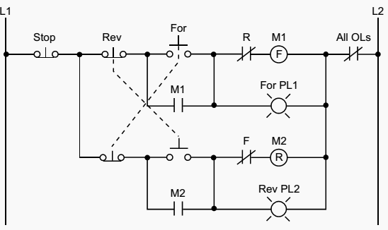
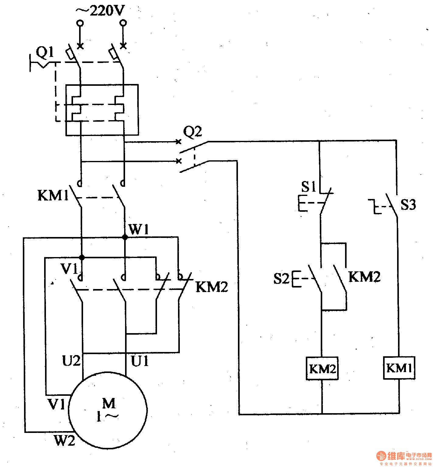
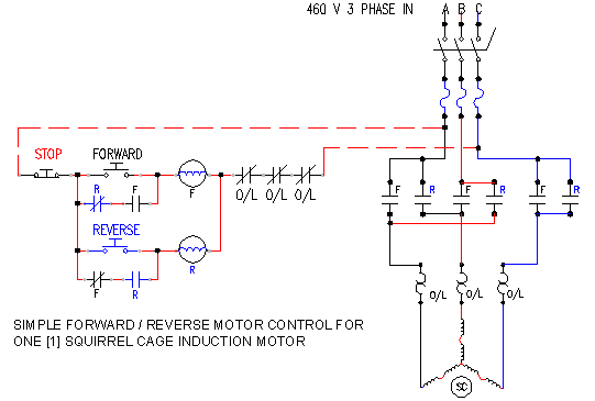
Forward reverse motor control. When it reaches the rightmost limit the drive motor reverses and brings the workpiece back to the leftmost position again and the process repeats. The forward reverse motor control is used i a system where forward and backward or upward and downward movement in the operation are needed. These two normally open push button switch shown with green color. For three phase motor forward reverse control circuit. In the diagram i shown also a light indicator which will be. The reverse contactor coil gets supply through phase r off push button f2 reverse contactor coil r on push.
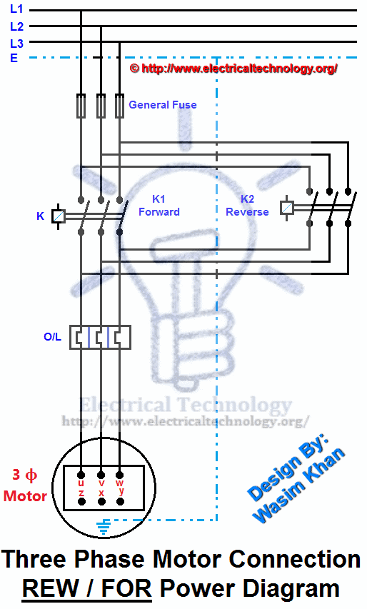
Your ac motor must be designed for reversing not all ac motors can be reversed without additional provisions. These forward and reverse starters are dol type and not used above the 05 hp motors. The figure given below shows the control and power diagram of forward and reverse starter diagram. The forward and reverse pushbuttons provides a means of starting the motor in either forward or reverse so that the limit switches can take over automatic control. Plc example for motor. An example of which are shown in figures below a and b.
The forward reverse motor control is used i a system where forward and backward or upward and downward movement in the operation are needed. The forward reverse motor control is used in a system where forward and backward or upward and downward movement in the operation are needed. An example of which are shown in figures below a and b. We use 2 magnetic contactors as forward reverse switch. The workpiece starts moving on the left side and moves to the right when the start button is pressed. Forward and reverse operation of motor can be obtained by interchanging any two of its three terminals.
Forward green switch is use for to run motor forward and reverse switch is used for run motor on reverse mode. Here i showed the forward reverse wiring diagram. The red push button is for switch off the motor. As the name defines forward reverse starter is used to run the motor in both sides forward and reverse. However if an overload occurs the contacts in the plc program will open and the motor circuit will turn off. Reverse direction press on push button r on.
For the common reversing ac motor run your neutral wire directly to your motor the hot lead through the 1 2 terminals and your reversing leads through the 4 3 6 5 terminals. In the above reverse forward motor control circuit diagram. The forward and reverse motor commands will operate normally if no overload condition exists because the overload contacts will provide continuity. In the diagram i connect the incoming three phase supply l1 l2 l3 to the mccb circuit breaker molded case circuit breaker.
