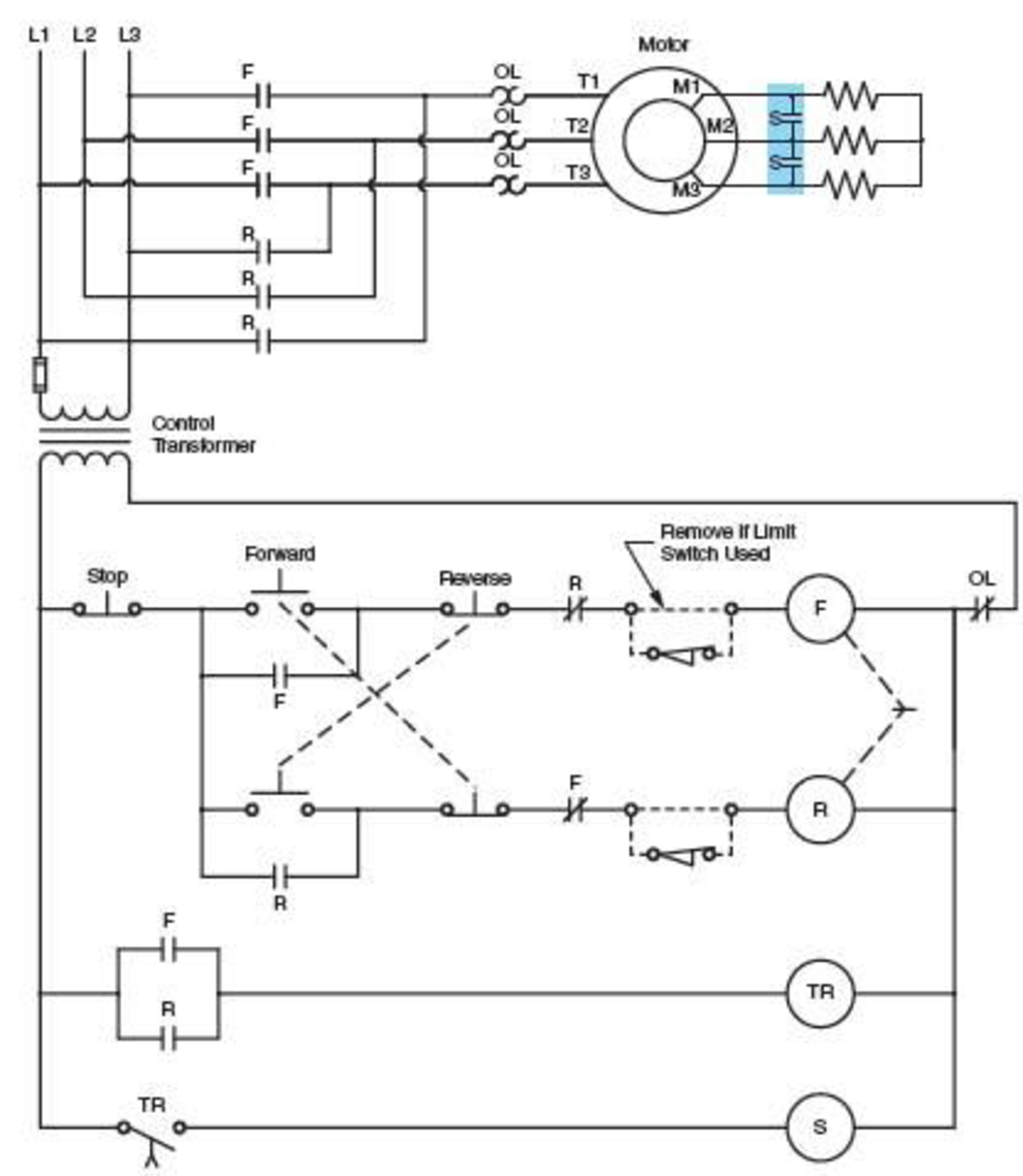
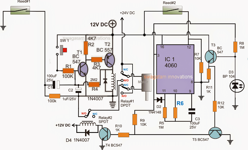
When the right limit sw is activated the relay coil is energized reversing the motor direction to the left. The interlocks are specially important because if both relays are on it would be a short circuit.

Controlling Stepper Motors With Hall Effect Switches
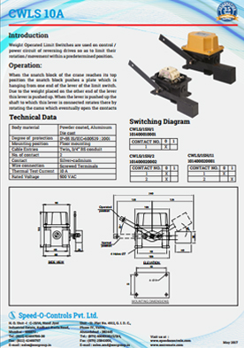
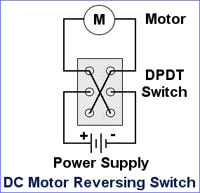
Dc motor reversing circuit with limit switches. It would be nice to add a couple of additional switches to automatically stop the motor when it has gone too far but still allow the operator to return the motor to an allowed position. It doesnt have interlocks or a stop button but it can all be added to it. Wiring diagram of a dpdt connected motor plus two snap action switches for user control with limit stops. Diode will allow motor to go in reverse direction. The circuit uses 2 relays 2 limit switches and a dc motor. Below is a simple circuit that should do what you want.
Diode will be reversed biased. The motor runs to the right with the relay de energized as shown. Normally upper and lower are closed but at limits one will open and shuts off motor. This is a minimal reversing circuit. Switch stops motor at limit and diode allows reversing of motor. It consists of a dpdt relay two spdt limit switches and 5 diodes.
It doesnt start on its own you have to push a limit switch.


