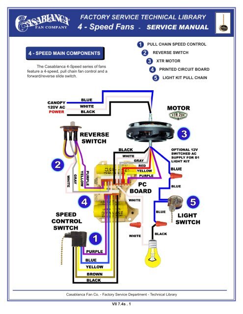
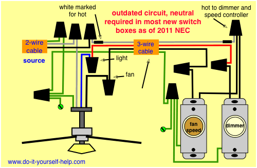
The fan control switch usually connects to the black wire and the light kit switch to the red wire of the 3 way cable. Ceiling fan wiring diagram 3.

Volvo Fan Control Wiring Diagram Diagram Base Website Wiring
Ceiling fan speed control wiring diagram. A wiring diagram is a streamlined standard pictorial representation of an electric circuit. A wiring diagram is a streamlined standard pictorial representation of an electric circuit. It shows the components of the circuit as simplified shapes as well as the power and also signal connections in between the gadgets. Ceiling fan wiring diagram 1. Take a closer look at a ceiling fan wiring diagram. Red speed switch two wire capacitor.
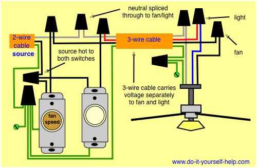
This wiring diagram illustrates the connections for a ceiling fan and light with two switches a speed controller for the fan and a dimmer for the lights. Assortment of ceiling fan speed control wiring diagram. Switched lines and neutral connect to a 3 wire cable that travels to the lightfan outlet box in the ceiling. Black speed switch with only three terminals connected two wire capacitor. This might seem intimidating but it does not have to be. It shows the components of the circuit as streamlined forms and also the power and also signal connections in between the devices.
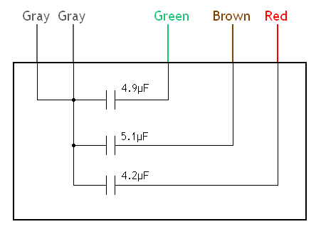
In the above ceiling fan speed control wiring diagram i shown the main winding running winding and i connect run wire of motor to the speed control switch and you can see it in above diagram that connection of run wire of motor in switch l point and and 1 and 2 for capacitor. It shows the components of the circuit as simplified forms as well as the power and also signal connections in between the devices. Assortment of ceiling fan wiring diagram 3 speed. Click on the image to enlarge and then save it to your computer by right clicking on. 2 to 1 2 med. Collection of canarm fan speed control wiring diagram.
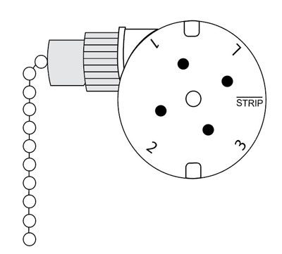
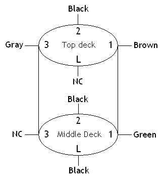
Pick the diagram that is most like the scenario you are in and see if you can wire up your fan. Speed switch connection table. I need a wire diagram for a 3 speed 3 wire switch and diagram of capacitor for a model tfp ceiling fan my guess is the capacitor is connected wrong and that is why i am only getting 2 speeds submitted. Variety of hunter 3 speed fan switch wiring diagram. With these diagrams below it will take the guess work out. Need step by step instructions on replacing ceiling fan.
A wiring diagram is a simplified standard photographic depiction of an electrical circuit. Ceiling fan wiring diagram 2. Black speed switch three wire capacitor. Ceiling fan speed control wiring diagram collection. 2 to 3 do not use an electronic speed control on this type of fan. No connection 1 fast.
2 to 1 and 3 3 slow. Hunter 3 speed fan switch wiring diagram 3 speed fan switch diagram best 10 ceiling wiring free at typical new 4 wires. From the switches 3 wire cable runs to the ceiling outlet box. The source is at the switches and the input of each is spliced to the black source wire with a wire nut. Ceiling fan switch wiring diagram 2 line voltage enters the switch outlet box and the line wire connects to each switch. 5 years agoceiling fan speed switch repairhunter fan speed control.
