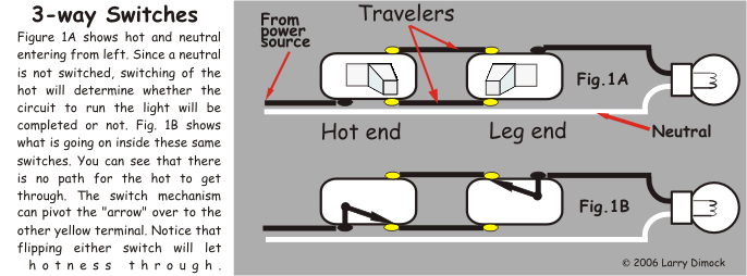
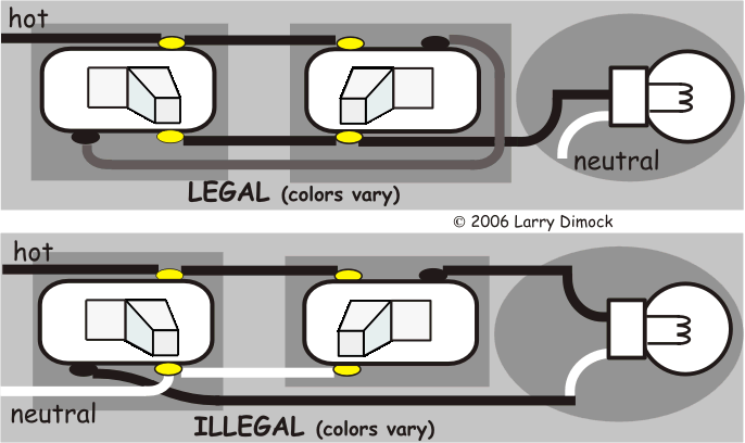
With these diagrams below it will take the guess work out of wiring. The 2 diagrams below shows a 4 way added into the traveler wires and yet the light stays on even after the 4 way switch is flipped.
3 Way Switch Troubleshooting Diy
California three way switch diagram. How to wire 3 way switch. Traveler wires are interchangeable. Many variations of this basic theme are possible. A 3 wire nm connects the traveler terminals of the first and second 3 way switch together. All three way switch and 2 way switch wiring diagrams have the same basic components. This might seem intimidating but it does not have to be.
Also called a california 3 way. The black line wire connects to the common terminal of the first 3 way switch. 3 way switch wiring diagram with power feed via light. Wires consisting of a line a load a neutral a pair of travelers and two 3 way switches. Typical 3 way switch wiring nm cable. For instance the 3 way switch schemes a b c above will allow a 4 way switch and box or any number of them to be interposed between the 3 way switch boxes.
The alternate 3 way switch wiring configuration california or west coast was used as a way to wire 3 way switches and be able to supply line voltage to either switchthis configuration is no longer allowed as the neutral is not present in each switch box. In the 1st diagram below a 2 wire nm cable supplies power from the panel to the first switch box. Conventional and california diagram. Now discussing 3 way light switch wiring diagram as also discussed above the color codes of the wires as having three insulated conductors as black as hot red as switch wire or called traveler and white as common wire as also shown when light is connected to both black and white wires. Conventional 3 way wiring is not very complexwith conventional wiring the line line voltage connects to the common of one switch. Three wire cable runs between the switches and 2 wire cable runs to the light.
3 way switch wiring diagram. If you are about to pull the wiring for a 3 way switch and you just want a basic method then use this most simple 3way switch wiring method s3 method 1. The black and red wires between sw1 and sw2 are connected to the traveler terminals. If you are trying to troubleshoot a 3 way switch operation then you will need to identify the function of each wire. As you can see this picture corresponds to the diagram for the basic 3 way switch system above. Take a closer look at a 3 way switch wiring diagram.
Pick the diagram that is most like the scenario you are in and see if you can wire your switch. Wiring diagram 3 way switch with light at the end in this diagram the electrical source is at the first switch and the light is located at the end of the circuit.


