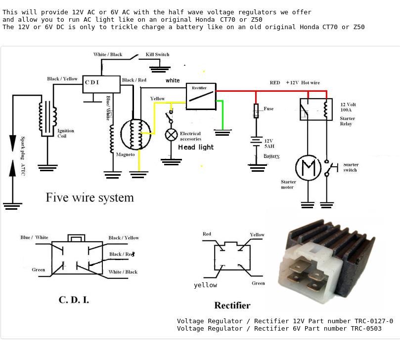
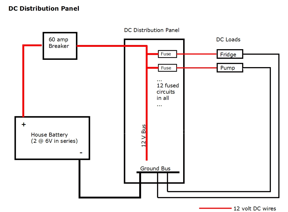
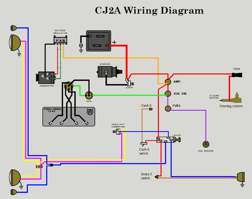
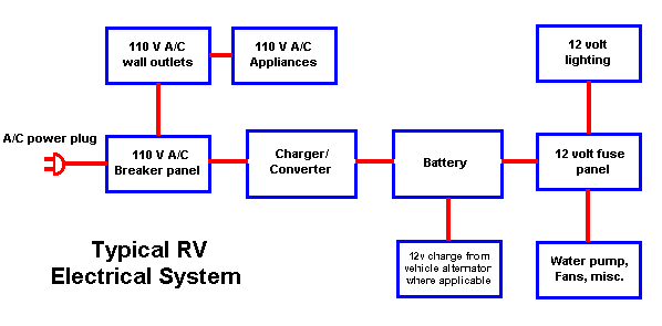
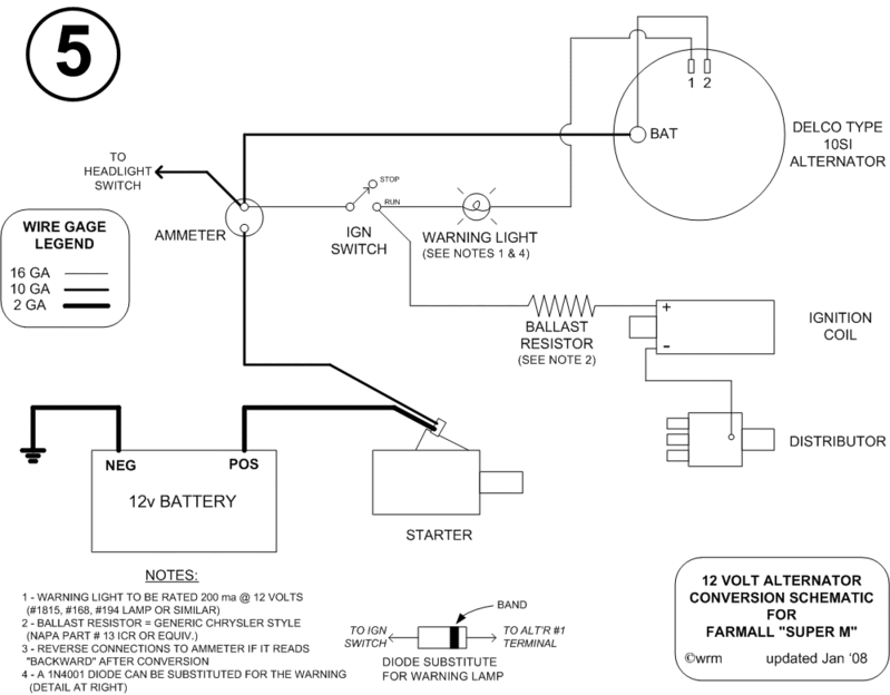
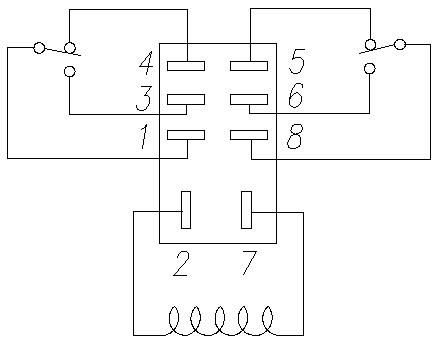
Basic 12 volt wiring diagram wiring diagram is a simplified pleasing pictorial representation of an electrical circuit. How to wire a 12 volt electrical system in an rv step 1.
Typical Wiring Schematic Diagram Boat Design Net
Basic 12 volt wiring. This type of connector is great for customer trailers. Diy solar power with will prowse 815626 views. For more information on marine 12 volt basics read electrical resistance on boats. In this case 05mm² 11a cable would be appropriate. Use a battery isolator to ensure the chassis system cannot be depleted by use of the coach systems equipment. It should not be carrying significant loads throughout the journey.
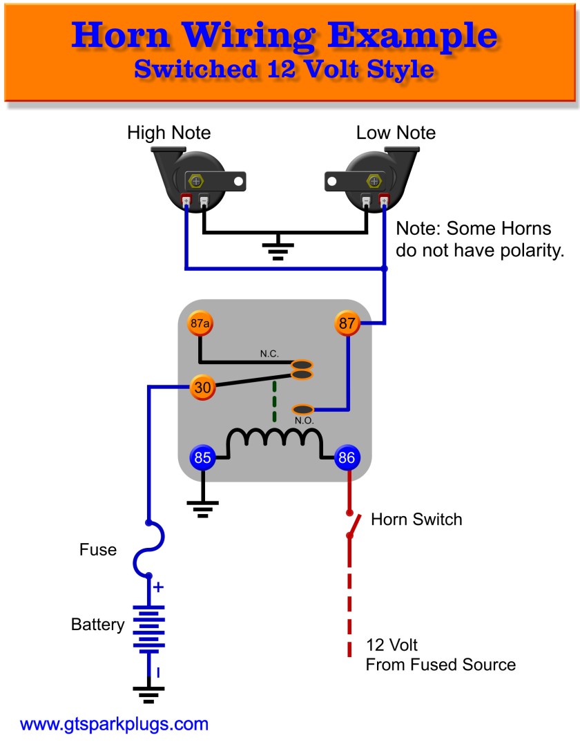
There is a really basic 12 volt trailer wiring diagram. Great for rvs and vans. It reveals the components of the circuit as simplified shapes and also the power and signal connections in between the tools. So for example if we wanted to wire up a light that we know has a power rating of 50w then the current draw would be 50w12v 417a. Assortment of 12 volt relay wiring diagram. It shows the components of the circuit as simplified shapes and the gift and signal friends amongst the devices.
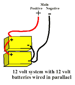
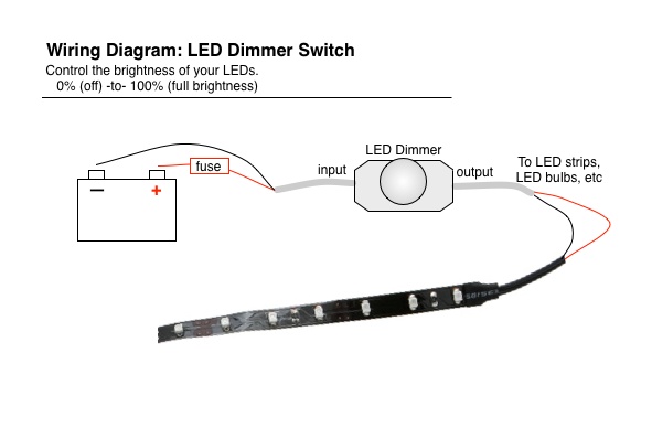
Those are the battery cables. Put the fixture where ever you are going to mount it and then run the wire however you are running it back. How to install a led light fixture step 1. Otherwise the structure wont function as it ought to be. Proper battery management including switching and charging is essential for safe and reliable operation. Design the coach system to safely answer all your predicted amperage and voltage needs for power outlets.
Keep that voltage drop in check and all about amperes in a boats electrical system. Basic 12 volt boat wiring diagram 12 volt marine wiring diagram basic 12 volt boat wiring diagram every electrical arrangement is composed of various unique components. Diy 400 watt 12 volt solar power system beginner tutorial. Each part should be placed and connected with other parts in particular manner. American boat and yacht council abyc standards permit a 3 percent voltage drop for critical. A wiring diagram is a simplified traditional pictorial depiction of an electrical circuit.
It is the 4 pin connector. This tells you that you could use a cable with a rating of 417a or above however it is good practice not to design a circuit operating at the upper end of the cables rating and so you should select a cable with some additional capacity. An understanding of basic boat wiring is a necessity for any boat owner or operator. Part 1 duration. The following basic wiring diagrams show how batteries battery switches and automatic charging relays are wired together from a simple single battery single engine configuration to a. Strip and crimp a butt connector to each wire coming off the light fixture.
Basic 12 volt wiring. Then strip and crimp a black wire to.
