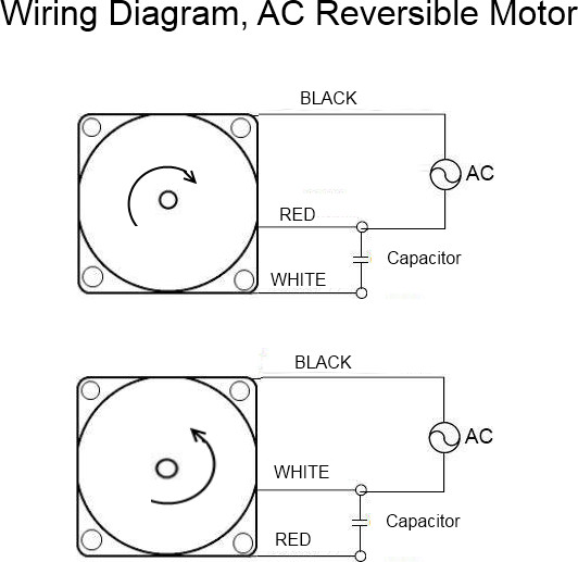
Consult the link below. How to wire an ac electric motor step 1.

4 Wire Ac Motor Wiring C3 Wiring Diagram
4 wire ac motor. Since most oem motors only have 3 wires and most replacement condenser fan motors have 4 wires this creates a little confusion. A 6 wire stepper motor is similar to a 4 wire configuration with the added feature of a common tap placed between either end of each phase as shown in figure 2. For groschopp 115 and 230 volt ac80 ac90 and ac100 single phase motors. Be absolutely sure all electricity is removed from the motor circuitry before wiring any ac motor. The common lead white and the brown with the white tracer contractor leads are wired into the same circuit so the brown with the white tracer can be cut off and insulated with a wire nut and electrical tape you dont need it. Connecting this motor type is very straightforward and simply requires connecting the a and a leads to the corresponding phase outputs on your motor drive.
A basic 4 wire stepper motor is shown in figure 1. 4 wire stepper motor 6 wire stepper motors. May not be accurate for other brands or. Simply wire the common lead white to the common terminal the contractor lead solid brown to the f terminal and whatever lead. As 183 4 wire reversible psc motor motor connection diagram for a 4 wire reversible psc. For ccw rotation transpose the blue and yellow leads.
Again this is ac power and not a dual capacitor so the terminal side does not. Check the motor manufacturers manual for recommendations on the correct wiring hookup for your application. Stepper motors with these center taps are often referred to as unipolar. Now for your 4 wire method. Schematic shows cw rotation facing the drive end. White wire from the condenser fan motor to one side of power on the contactor t1 black wire from the condenser fan motor to other side of power on the contactor t2 brown wire from the condenser fan motor to the capacitor.
Gallery of 4 Wire Ac Motor


