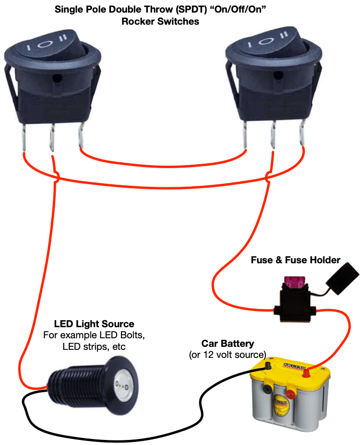
Such markings are not needed with this type of switch as they are. If you have ever wondered how this arrangement works and how each switch knows what the other switch is doing then read on.
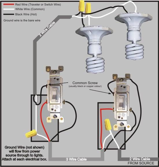
3 Way Switch Wiring Diagram
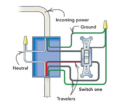
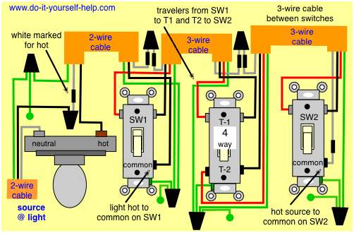
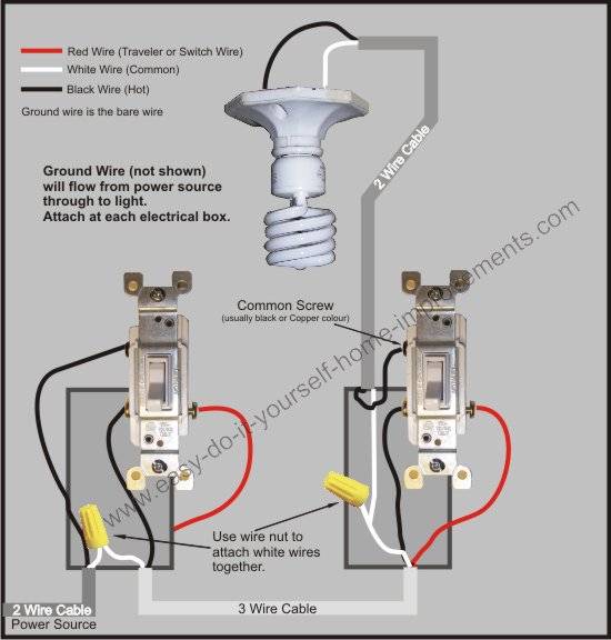
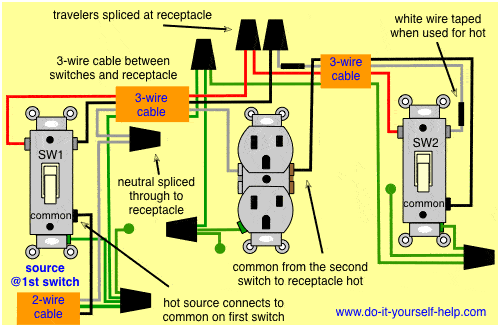
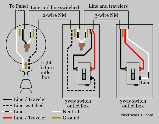
3 way switch explained. The 3 way switch was originally developed to allow users to control a light from two different locations. The two hot wires of three wire cable connect to a pair of brass colored traveler terminals on each switch. For more than two switches one or more 4 way switches are added. This is known as the common screw and its usually black instead of brass or silver. A third type is the four way switch which is used in conjunction with two three way switches to control lighting from more than two locations. In this diagram the incoming hot wire attaches to the first switchs common dark colored terminal.
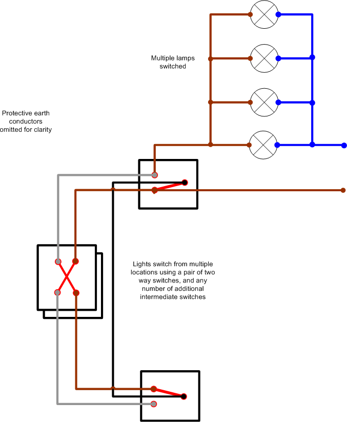
There are two clear giveaways that identify a switch as being a three way type. A regular switch has only two connections and simply cuts the flow of electricity through the switch or allows the current to pass through it. A three way light switch is different than a traditional single pole light switch as it contains an extra screw to connect an extra wire. This configuration may be used in open plan homes or in large kitchens or great rooms where a central bank of lighting fixtures might be controlled from more than two entry points. How 3 way and 4 way switch circuits work controlling a light with two or more switches. There are no onoff markings on the switch toggle.
A 3 wire nm connects the traveler terminals of the first and second 3 way switch together. This requires a special switch. This terminal is usually identified by a darker colored screw. The key to wiring 3 way switches the power feed and the switch leg leading to the fixture s typically one at each switch location are attached to the screw terminal found at one end of the switch by itself. Whenever you flip either one of the switches the light changes its state if it is on it turns off and if it is off it turns on. Controlling a light with three or more switches.
The black line wire connects to the common terminal of the first 3 way switch. Typical 3 way switch wiring nm cable in the 1st diagram below a 2 wire nm cable supplies power from the panel to the first switch box. This 3 way switch wiring diagram shows how to wire the switches and the light when the power is coming to the light switch. Another dead giveaway of a three way switch is the absence of on and off markings. When the switch is on current flows along the black wire through the switch to the light and then returns to ground through the white wire to complete the circuit. In this article we will solve the mystery of three way switches.
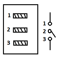
This page describes how to use 3 way and 4 way switches to control lights. The three way switch is a variation of the standard single pole switch which controls a light only from one location. Three way switches each have three connections and are used in tandem. There are three screw terminals on the body of the switch in addition to the green grounding. The switch simply opens off or closes on the connection between the two terminals on the switch.







/Three-WaySwitch-56a27f675f9b58b7d0cb52c8.jpg)
