A relay is basically a switch but not like a switch thats on a wall. 5v 6v 9v 12v 24v dc motor.

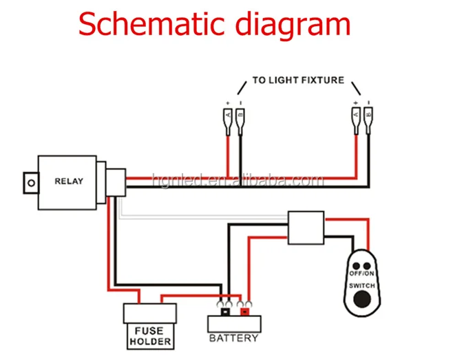
C4d08e6 Light Bar Wiring Diagram 24v Wiring Resources
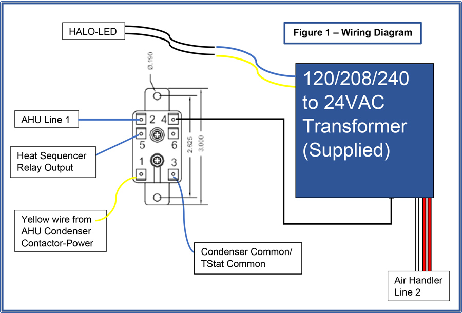
24v switching relay wiring diagram. Old low voltage wiring electrical systems use. I have the aube rct and was going to use on the profusion eh w november edited november in a c heat pumps refrigeration the heater shows wiring diagram if i was using a line voltage with two heaters relays and one tstat using the honeywell relay rct aube rct. Wiring diagram replaces 710890areplaces 710890a l2 l1 t2 t1 g n t4 l t2 t3 c t5 t1 y1 l1 l2 ecm y2 c 4 3 2 1 8 7 6 5 9 lrc y2 o w2 in w2 out df1 ambient ambg coilg coil demand defrost control board rev y valve hps lps y out y2 out c r s h c f reversing valve coil daul capacitor outdoor motor compressor trasformer 240v 24v high speed blower relay 24v blower relay blower motor com red black black brown blue compressor contactor black black yellow yellow yellow black yellow black see. Read our guide to relays found in vehicle electrical systems. The wiring diagram and instructions might be confusing for the lay person but if you. Omron ly2 relay wiring diagram socket relay omron socket relay omron suppliers and manufacturers at alibaba.
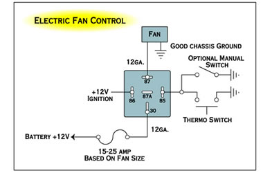
Assortment of 24vdc relay wiring diagram. Confirm the operation by measuring the continuity at the line voltage terminations of each relay. Relay wiring diagram used for accessories in a 12volt systema relay is typically used to control a component that draws high amperage. Use relay logic to control lights using relays in standard applications as well as 3 way switching application. Variety of omron ly2 relay wiring diagram. 3 bluetooth v21 edr class 2.
Sr8 industrial control relays sr8 miniature power relay applications. Low voltage relay wiring diagram. It shows the elements of the circuit as simplified forms and also the power as well as signal links between the devices. I am using 24vdc relays to switch 240vac 15ampon irrigation line. Our relay logic guide. A relay is switched by electrical power and not a human.
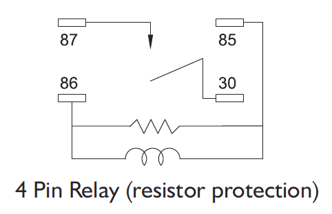
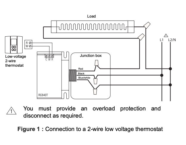
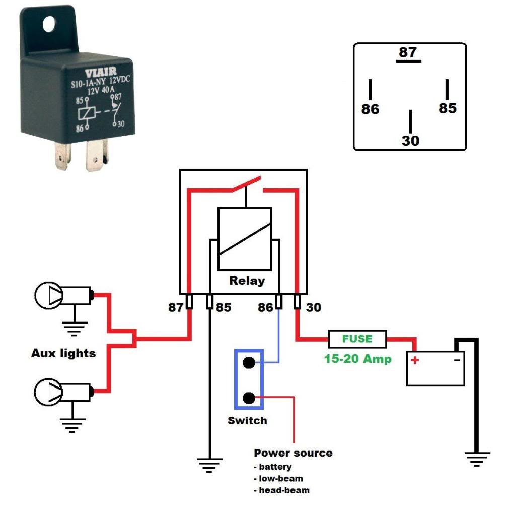
Buy aube rct onoff switching electric heating relay with built in 24 v transformer. This is done by energizing a coil which is internal to the relay and by energizing the coil the relay changes state just like a wall switch would. A simple single line changeover switch is achieved by switching a single line input from terminal position 30 at rest in the normally closed terminal position 87a indicated by the thick set black lines on the diagrams below to the 87. 10 relay maximum load10a250vac 10a125vac10a 30vdc 10a 28vdc 10a 12vdc. 7 external trigger input opto isolated switch low pulse inputs. Click on the image to enlarge and then save it to your computer by right.
All low voltage components operate using 24 volts furnished by the step down transformer. Wiring diagram sheets detail. This page demonstrates several simple ways to wire a relay for various applications. A wall switch relies on someone to flip it which will then control a light or some other type load. Use relay logic to control the forward or reverse direction of motors. The most common changeover function relays are produced to switch a single feed line usually positive position 30 between two active functions in a circuit the relay is switched manually via a togglepush switch or remotely through the circuit.
Therefore when you energize a relay you are switching circuits off and on. Relay logic provides you with a guide for using ncd relay controllers and how they can be wired for many types of applications. To activate one or more relays that then complete one or more other circuits and so carry outindustrial control relays sr8 miniature. A wiring diagram is a streamlined standard photographic representation of an electrical circuit. Sold by jds electrical supplies and fulfilled by amazon. Relay logic is all about wiring up relays for logical switching applications.
The voltage should be measured at the field power connection point in the unit and while the unit is operating at full load maximum amperage operating condition.

