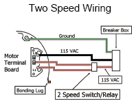
It reveals the components of the circuit as simplified shapes and the power and signal connections in between the tools. How to wire a volt 2 speed pump with breaker and disconnect is illustrated in this wiring diagram.

3 Phase 2 Speed Motor Wiring Diagram Camrysde 7
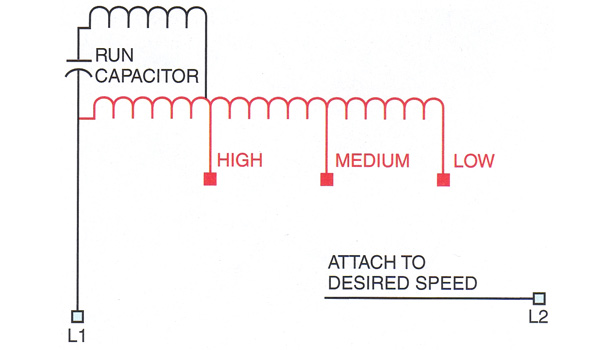
2 speed motor wiring diagram. A 2 speed pump requires using two relays inside the pro logic box. Additionally the low speed coil is typically supplied by a red wire while the high speed coil is fed by a black wire. This differs from a schematic representation. Collection of ao smith 2 speed motor wiring diagram. Two separate windings designed to rotate the motor at two different speeds or inbuilt resistors which alter the voltage supplied to windings. Kindly email me the diagrams for star deltor and direct online for a 3speed 1directon 3ph motor have two of them in a bow cutter.
Steps explain how to connect check out our recommended wire size chart for gauge requirements. Assortment of century 2 speed motor wiring diagram. I have purchased model. Two speed motor wiring basics since a two speed motor relies on different coils to produce different speeds there are usually two input wires. Please help how to go about this. Adjoining cable courses might be revealed around where certain receptacles or fixtures need to be on an usual circuit.
How to wire a 2 speed motor to a hayward pro logic system. In many instances the low and high speed coils share an external wire. Two speed electric motors operate in one of two ways. It has four terminals. Century 2 speed motor wiring diagram architectural electrical wiring diagrams show the approximate areas and also affiliations of receptacles lights as well as permanent electrical services in a structure. However the wiring to the motor is the same.
The electrical icons not. One terminal is the ground another common and the third and fourth are for fast and slow speeds. Wire a single pole double throw spdt switch into the circuit between the motor and the wall socket and you can change the. A wiring diagram usually offers info regarding the relative placement as well as setup of tools and also terminals on the devices in order to help in structure or servicing the device. It shows the components of the circuit as streamlined forms and the power as well as signal connections in between the gadgets. A wiring diagram is a simplified conventional pictorial depiction of an electrical circuit.
A wiring diagram is a simplified standard pictorial representation of an electric circuit. Electrical wiring diagrams make use of conventional icons for circuitry gadgets typically various from those used on schematic layouts. 3ø wiring diagrams 1ø wiring diagrams diagram er9 m 3 1 5 9 3 7 11 low speed high speed u1 v1 w1 w2 u2 v2 tk tk thermal overloads two speed stardelta motor switch m 3 0 10v 20v 415v ac 4 20ma outp uts diagram ic2 m 1 240v ac 0 10v outp ut diagram ic3 m 1 0 10v 4 20ma 240v ac outp uts these diagrams are current at the time of publication. One contactor burnt for high speed and a replced contactor does not engange originally the coils re fed with a nutural and the one i replaced is only working with a phase.


