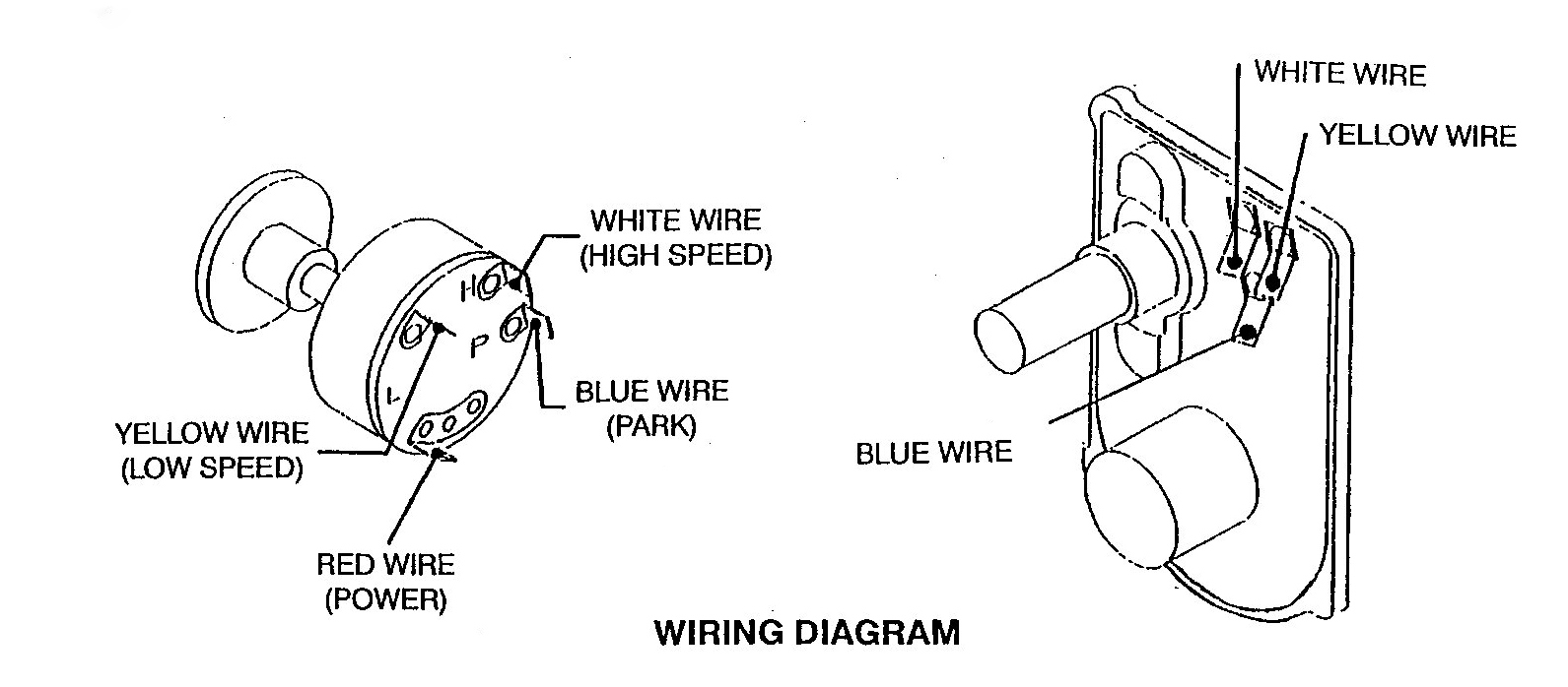
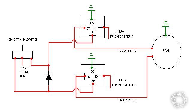
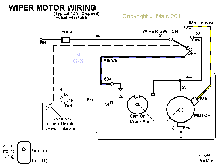
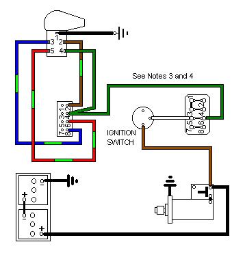
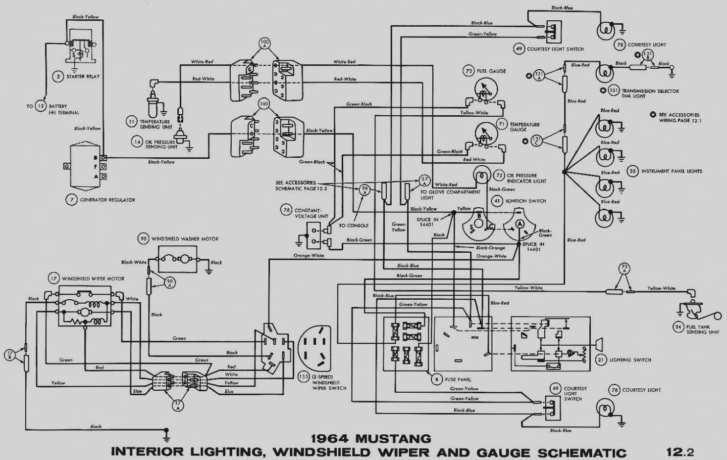
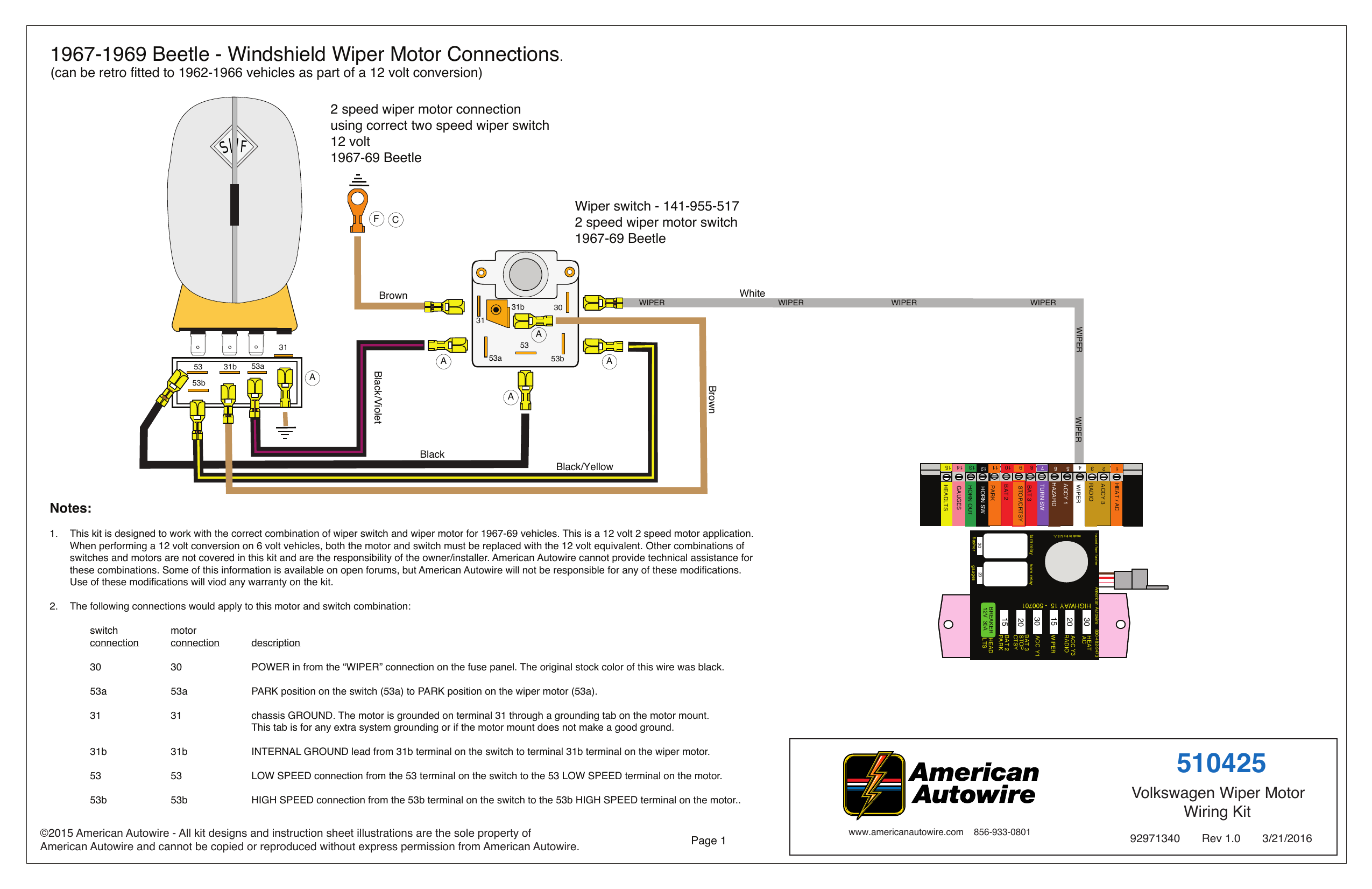
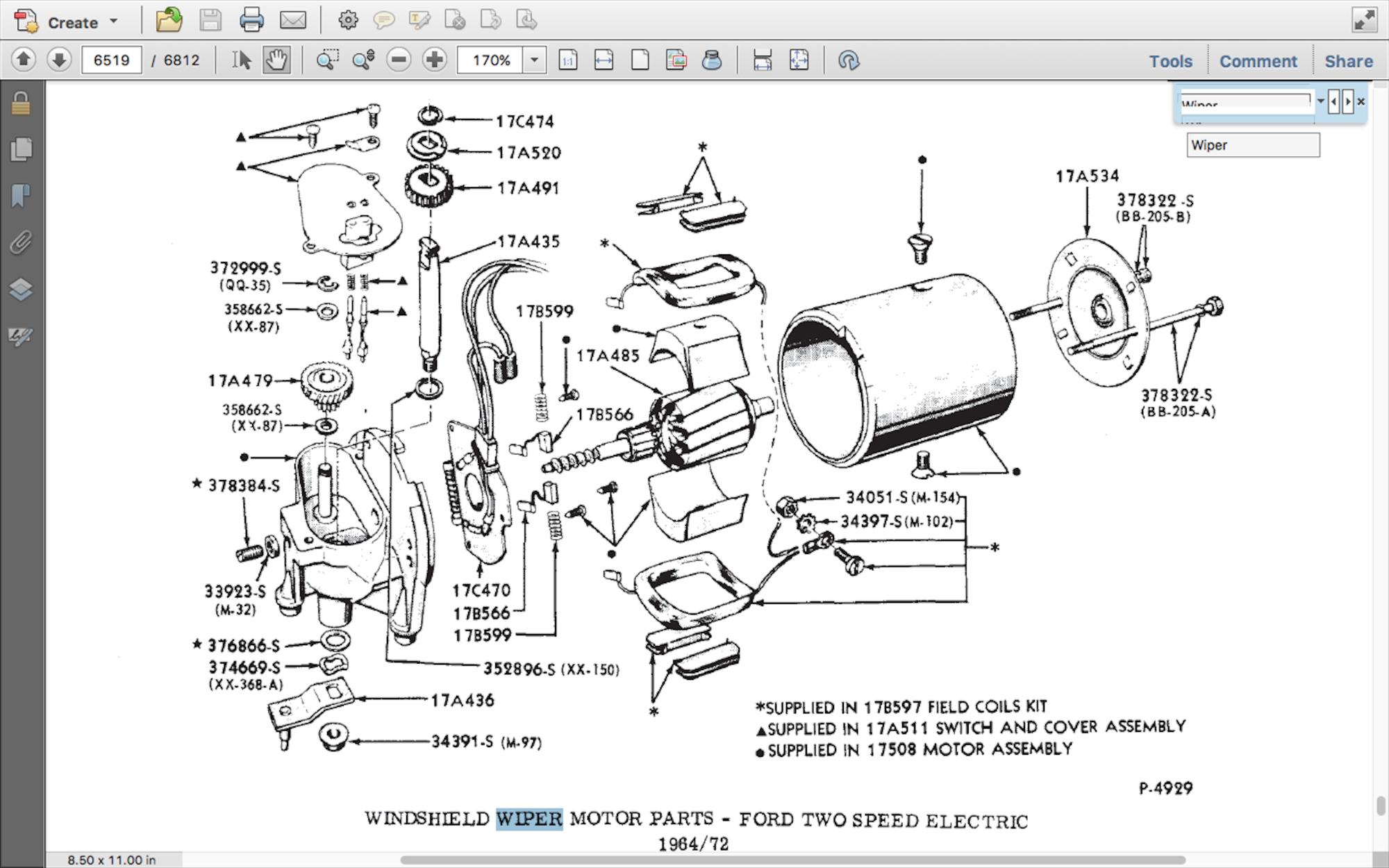
Please help how to go about this. However the wiring to the motor is the same.

2 Speed Fan Switch Wiring Diagram 3 Speed Fan Switch 4 Wire
2 speed motor switch wiring diagram. One contactor burnt for high speed and a replced contactor does not engange originally the coils re fed with a nutural and the one i replaced is only working with a phase. In many instances the low and high speed coils share an external wire. A wiring diagram is a simplified standard pictorial representation of an electric circuit. If youre having trouble installing the ez wiring universal wiper kit then you need to check out this tech article. Wiring diagram for two speed moto explained. The timer is activated from.
Universal 12v timer relay providing a 5 second delay for an intermittent wiper function. Painless performance universal windshield wiper switches. Kindly email me the diagrams for star deltor and direct online for a 3speed 1directon 3ph motor have two of them in a bow cutter. Wire a single pole double throw spdt switch into the circuit between the motor and the wall socket and you can change the. One terminal is the ground another common and the third and fourth are for fast and slow speeds. Going on a trip tomorrow and they call for some rain so id like to get it working.
Collection of ao smith 2 speed motor wiring diagram. Has anyone installed the speedway 2 speed wiper motor and switch. It shows the components of the circuit as streamlined forms and the power as well as signal connections in between the gadgets. Two speed motor wiring basics since a two speed motor relies on different coils to produce different speeds there are usually two input wires. Power and control circuit for 3 phase two speed motor. Guys do i have.
Two separate windings designed to rotate the motor at two different speeds or inbuilt resistors which alter the voltage supplied to windings. It has four terminals. Two speed electric motors operate in one of two ways. Like subscribe and dont skip the ads siemens logo tutorials. Universal wiper switch wiring diagram. Additionally the low speed coil is typically supplied by a red wire while the high speed coil is fed by a black wire.

