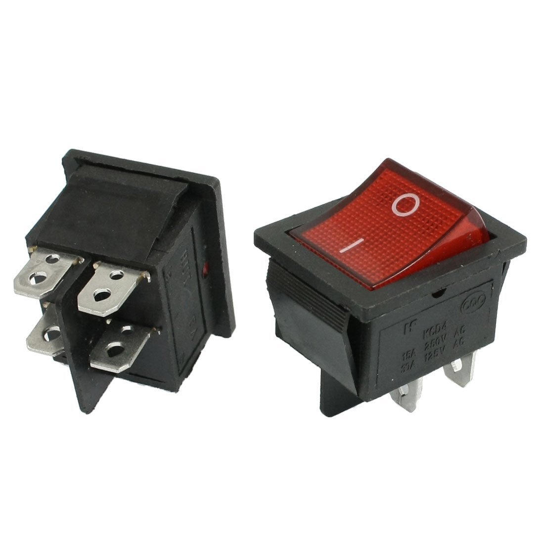
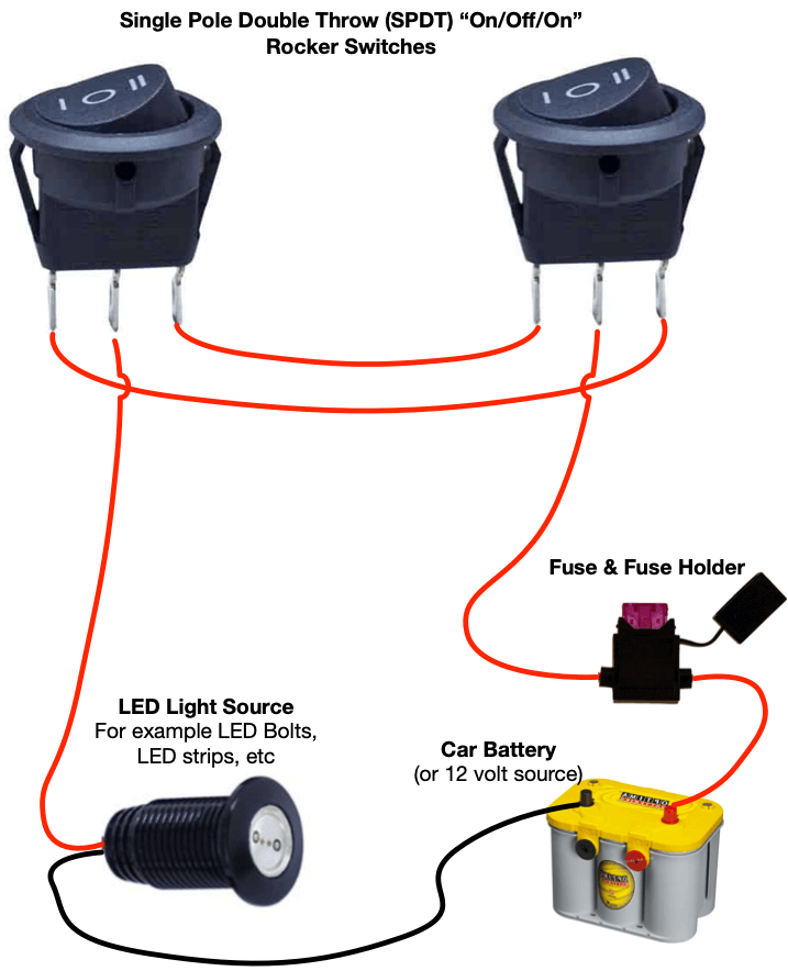
4 pin rocker switch wiring diagram 240v 4 pin rocker switch wiring diagram 4 pin illuminated rocker switch wiring diagram 4 pin led rocker switch wiring diagram every electric structure is made up of various distinct parts. With independent lamp circuit only 3.
Understanding Toggle Switches
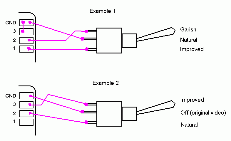
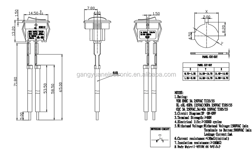
2 pin rocker switch wiring diagram. How to wire a 2 prong onoff toggle switch. This rocker is perfect for an engine offrunstart switch. 5 pin relay wiring diagram 5 pin relay wiring diagram 5 pin relay wiring diagram 87a 5 pin relay wiring diagram driving lights every electric structure is composed of various unique components. 4 pin rocker switch wiring diagram free picture manual e books 5 pin rocker switch wiring diagram. Wiring diagram contains several detailed illustrations that show the link of varied products. 3 pin rocker switch wiring diagram.
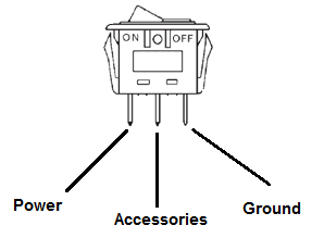
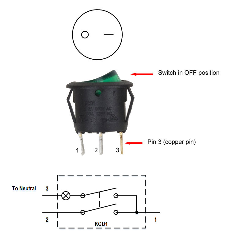
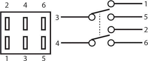
4 pin rocker switch wiring diagram 4 pin led rocker switch wiring diagram f diagrams toggle 240v and. 5 pin rocker switch wiring diagram. As you see in the schematic diagram of 2 way switch circuit below you will find that the phaselive is connected with the common of the first 2 way switch. Rocker switch wiring diagram. Otherwise the structure will not function as it should be. Pin 2 is where the accessory that the switch is going to turn on is connected.
Each and every. Below youll find a basic onoff rocker switch wiring diagram as well as an easy to understand illuminated rocker switch wiring diagram so no matter what your needs after reading this youll want to put switches on all your leds by yourself. It includes directions and diagrams for various varieties of wiring methods as well as other items like lights windows and so forth. Rocker switch wiring diagram. I had nothing to do so i made this quick how to video. Now that you have an idea how rocker switches are constructed internally lets go over the wiring diagram so.
It is off at the bottom on in the center and momentary on at the top. Variety of 4 pin rocker switch wiring diagram. And you can because its so simple and youll find everything you need to know about it right here. The diagram below represents the schematic diagram for a spst rocker switch. Or called a 2 pin switch. Buy these onoff switches from oznium.
Here i use a 2 prong switch for my horn siren. Pin 3 is where the switch is either connected to ground or left open. Pin 1 is where the rocker switch receives the input power. With just a few small jumpers our switch selection can be used for a multitude of different functions. This is the most basic type of switch the onoff rocker switch as shown using ozniums black anti vandal. Click on the image to enlarge and then save it to your computer by right clicking on the image.
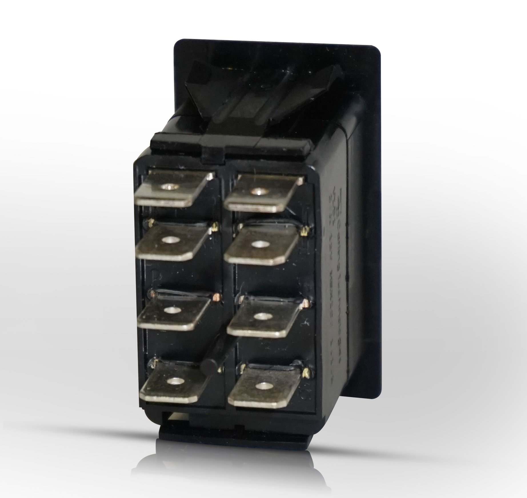
The e book incorporates a great deal of sensible tips for different circumstances that you could encounter when you are dealing with wiring issues. We have more then 20 years in on off rocker switch manufacturingand have got 2 invention patents and 47 utility model patents. This is a rocker switch body only. Each part should be placed and connected with different parts in specific way. Now that you have an idea how rocker switches are constructed internally lets go over the wiring diagram so that you will now. With lighting sequences 10 20 30 4050 only.
How to wire a 2 prong rocker switch. Pin1 pin2 of the first switch is connected with the pin1 pin2 of second switch respectively.

