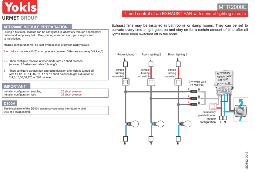
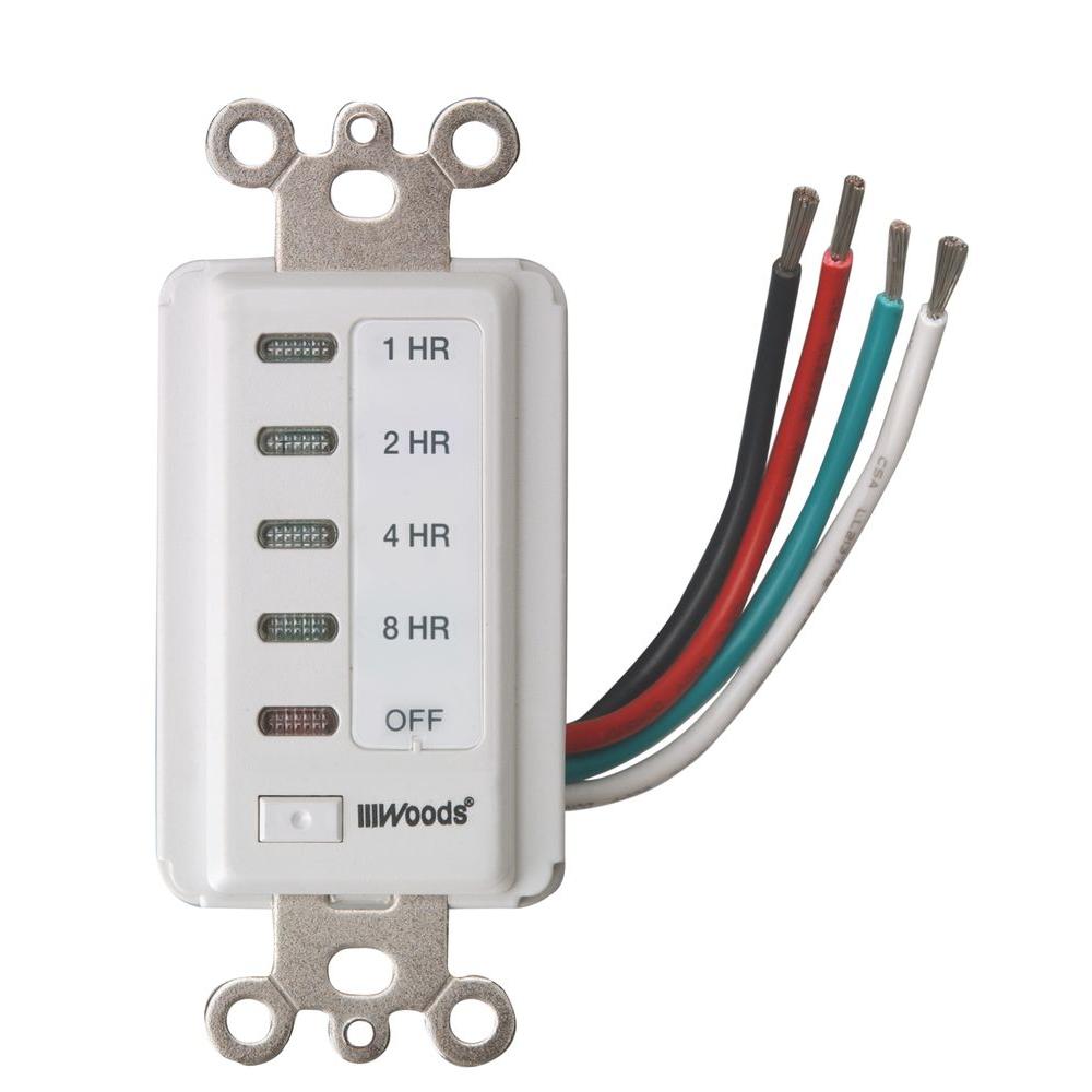
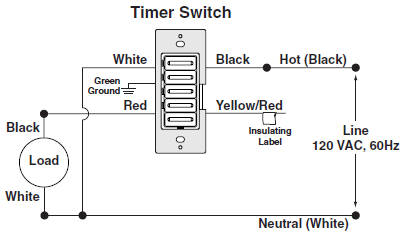
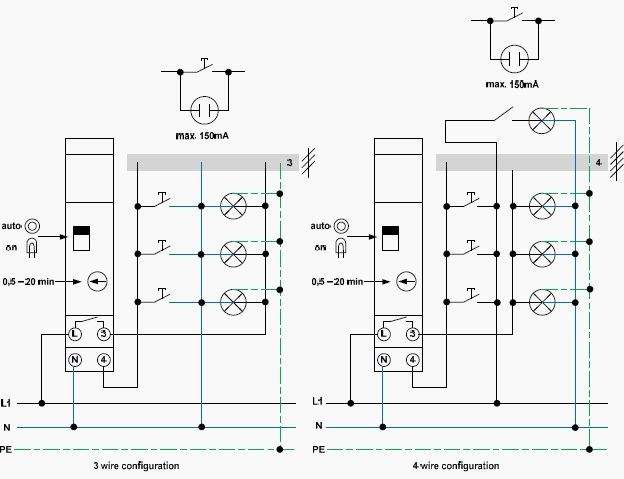
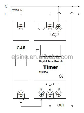
This timer is generally use when we want to control our load on and off as we. Do not exceed the wattage rating for the load on these switches.
Introduction To Lighting Controls
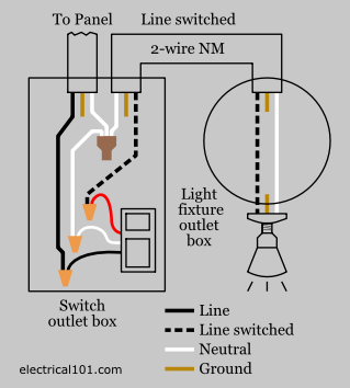
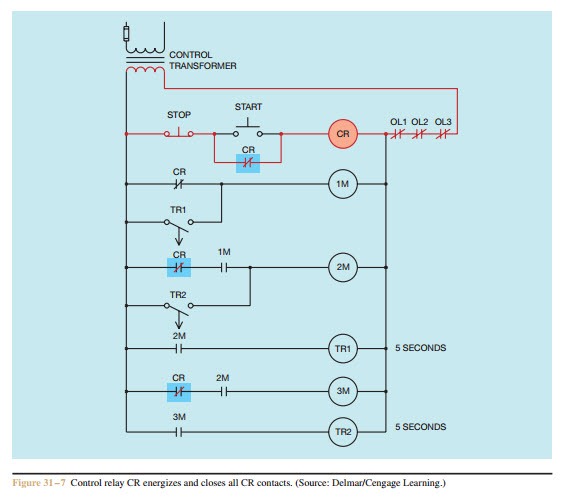
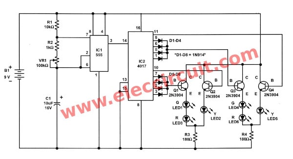
Lighting timer control diagram. Timers are used to control fans water pumps irrigation controls etc. Timer mechanisms settings and indications of timers. A timer is a control device that outputs a signal at a preset time after an input signal is received. Home automation and light switch wiring electrical question. Ceiling light turns on when the door is opened. A wiring diagram is a straightforward graph of the physical connections and also physical format of an electrical system or circuit.
The timer keeps zeroing out to the flashing initial setup screen after about 5 or 6 toggles of the other light switch in the box. Photocells and timers have a wattage rating. On delay timer circuit diagram wiring diagram contactor with push button circuit diagram of delay timer on off power off delay timer circuit diagram 2 way lighting circuit triggering transformer push button fan switch light activated switch circuit diagram wd081 text. Pool light transformer wiring diagram new pool timer wiring diagram exactly what is a wiring diagram. Each component should be placed and linked to other parts in particular manner. Photocells are commonly used to control lighting.
What is a timer. The light remains lit for several seconds after you get into the car and close the door. In this video we explain street light timer or 24 hour street light timer setting and connection with practically. Photocells and timers are switches that turn on and off automatically. Im trying to replace a single pole light switch with a timer light switch in a box that also has another single pole switch going to another light.
